Usage and Commands
Screenshot
UsageWorkplace organizationThe info/edit panel
Templates organization
Useful hints
Manual editing
Manual clipping
Groups
The grid
The magnetic guides
Selections and super selectionsThe Items List panel
The info/edit panel expanded
The Color Management Panel
The preferences panel
Environment preferences
Pasteboard behavior preferences(outdated since v. 3.5)
Insertion preferences
Nesting preferences
Attributes preferences
The tools
Specialized tasks Image Adjust
Serial Duplication
Change from a scale to another
Object transformations
Nesting
Contact sheet
Trimming sheet
Expand PDF
Pagination
Imposition (booklets)
Imposition business cards
Advanced insertion
Tracking print work
Ink consumption evaluation
Send PDF to FitPlot from other Apps
Image Capture
Import from Connected Devices…
Acquire from Scanner…
Revert Stack Order…
Resize to Photo Standard Sizes
Export to PDF
Export to Bitmap
Export Single Image
Export as TIF 16bit@300dpi…
FitPlot is a layout program for images / PDFs. Here you can import almost any kind of graphic file (jpg, tif (also multipage), tga, gif, png, psd, eps and PDF (also multipage)).
Tip: it is possible (from version 3.5) to insert images or graphical objects (mix of text and graphics) simply copying them from other apps (a graphic program, for example) and pasting them into a FitPot document area.

Usage
Simply talking, the program is very intuitive. To import an image you can either insert from the file menu or by the insert tool
![]() in the toolbar (we will see the toolbar later), but the simplest way is to use drag&drop: select one or more images file on your disk and drop them on the FitPlot white area. You can also drag and drop images from another program or even from the web (drag from browser).
in the toolbar (we will see the toolbar later), but the simplest way is to use drag&drop: select one or more images file on your disk and drop them on the FitPlot white area. You can also drag and drop images from another program or even from the web (drag from browser).
Note: you can perform some automatic operation while importing images (resize, rotate, apply styles, automatic nesting). This can be useful in cases such importing a folder of images for a quick print of previews. See insertion preferences here.
Once on the FitPlot area images can be modified in their size and orientation, can be clipped to make some part disappear, can be placed everywhere, even out of the working area. Can be moved back and forth the image stack and you can apply them some style as trim marks, dashes and strokes, shadow and transparency (only for PDFs and raster images with an alpha channel such as png or tiff), show tag with file name, date, size and path.
Workplace Organization
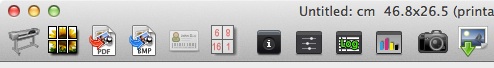
The main window is organised in this way:
- The window title:

it contains informations about the name of the document and the current page size (bracketed the printable area size, according to the margin settings, see installation -> test your printer).
- The toolbar: just below the window title, the toolbar hosts useful FitPlot command, at a mouse click.
Fully customizable to your needs. See toolbar paragraph here.
- The quick page size controls:

(it is quicker compared to the usual page setup menu as usual there in the File menu);
the page setup... button has the same function of the File -> Page Setup... menu and is a quick way to have at hand all sizes proposed by the installed printer drivers.
Custom size fields and SET push button allow the setting of any custom page size.
- Units popup
More centered you can see the unit of measure control
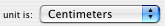
you can choose from centimeters, inches and points.
- Toggle pagination drawer:
 at the extreme right there is a little button, grayed by default, that is used to open the pagination drawer. This button is enabled only if you set the FitPlot document to more than just the single default page. (See pagination for further explanations).
- The zoom control (a slider with three buttons, the left one for the min, the right for the max and the center arrow for the 1:1 zoom)

lets you resize your view of the sheet from a minimum of 0.01x (click to the left) to a maximum of 100x (click to the right), passing through intermediate values.
A shortcut is available on the keyboard (click with the mouse while holding down space+command keys to obtain a one step zoom+, click with the mouse while holding down space+command+option keys to obtain a one step zoom-). With the same keys combination, but dragging the mouse, you obtain a box-zoom, that means the boxed area will fit the visible area (zoom in).
Furthermore you can live zoom using the mouse scroll ball (or scroll wheel) while holding the alt (option) key.
- The "sheet" area:

this area, surrounded by the vertical and horizontal rulers, is where you make the layout of the objects to print. Drop here images from your disk or from another application, move, resize clip etc.. The area represents the sheet your printer will paint on.
In this area may be activated a visible grid to snap images on (see grid) either you can use movable magnetic guides (see guides).
You can control the editing manually with the mouse or more precisely with the info / edit panel.
Other object manipulations can be done with some commands in the toolbar.
Useful hints
- Choose plotter sheet size from the usual File -> Page setup menu.
- Save / reopen arranged sheets for later time printing. Margins and paper sizes are saved along with the file.
- Save and open as template. You can collect your documents as models for future use.
To know how to organize the template's folder take a look at Templates organization.
- Drag and drop your files from Finder or other program to the sheet area.
- Easily move the objects with a grid snap (tools -> grid menu options).
- You can finely move a selected object also with arrow keys (1 pt x step). This is influenced by the snapping on the grid too. The movement amount is equal to a grid step at each keys stroke. Pressing the shift key increase of x5 the value of the arrow movement.
- Move. You can use the tools->move menu (command-M) to move all selected objects. A dialog (see figure below) lets you input the deltaX and deltaY values. Just remember that Y values increase from top to bottom of the screen (as the represented plotter sheet first part to come out is the upper one).
There is also a way to move objects around pages (if more than one page is available in the document).
While moving by dialog you can optionally make a copy of what you are moving.
- Drag copy (alt key pressed) while you click and drag an object. Mouse cursor will change this way
 . A copy will be created at the point where the mouse is released.
You can drag an object and drop it on a page in the pages drawer (available when the document has more than just one page).
While drag-copying (alt key pressed) a copy of the moved object will be placed on the page where it is dropped, maintaining the same relative position on the new page. A drag-move (alt+cmd keys pressed) will move the object as above, without copying it.
- Another way to duplicate an object: edit -> duplicate menu (command-d) or the tool
 in the toolbar.
- To delete an object: edit -> delete menu (cmd+backspace[←]) or use the delete tool
 in the toolbar.
- Styles. To give an object border, trim lines etc.: tools -> object print styles (or use the info panel, style popup).
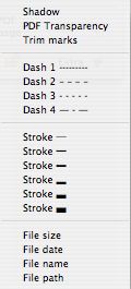
Styles can be applied to an image to put trim marks at its corners, set a shadow, frame it with a stroke or dashed line of various thicknesses, add a tag with file name, file date, file size, file path or a custom text.
The caption text can be showed on any side of the image (see info panel extra).
You can apply even transparency to PDF. PDF usually have their white background set to no-print. You can use this characteristic to superimpose a PDF on a background and make other peculiar tricks as in the scenario 4 example.
Tip: Transparency is supported also by eps and by raster images that own an alpha channel. We can find an alpha channel in images of the kind tiff, gif, png, psd.
- You can arrange object in the usual Mac way (tools -> bring to front, send to back etc.).
- Contextual menus (right click with mouse) on objects to access most of the above operations.
- Move around your view clicking the space bar (as in common graphic programs, the cursor become a
 ).
).
- Double click on any image in the view. This cause the file browser to open in search of an image to replace the double-clicked one. If more copies of the image you are replacing are present in the same document, you'll be asked by a dialog if you wish to replace just the double clicked one or all the set found.
Manual editing
To activate manual editing, click on the icon
![]() on the toolbar. Once activated, the icon should change in
on the toolbar. Once activated, the icon should change in
![]() (manual editing ON). To toggle it OFF, click it again.
(manual editing ON). To toggle it OFF, click it again.
With manual editing OFF you can only use the mouse to move the objects (click and drag), this is more practical, if you want not to resize / rotate, because the object area is all reserved to this and, especially with small images (or low zoom) and manual editing ON, it could be difficult to find space to move an object via click and drag.
Instead, with this option enabled, you can freely resize and rotate images around a chosen "
![]() "pivot.
"pivot.
Selecting an object, 9 handles appears on the image borders (and center). Around the handles there are sensible areas (see screenshot above) where you can see your mouse cursor change according with the operation you can perform on that object. Click and drag to perform operation in real time.
Operations are:
| resize | rotate | clip | |||
| set pivot | move | reposition |
Manual clipping
you can manually clip an image just clicking and dragging the side's handles.
While approaching the image side's handles with the mouse (with manual editing on), your cursor changes in
Click and drag toward the center of the image to clip the image. Note that in FitPlot versions previous to 2.2 these handles also was for resizing (![]() ). Now resizing is possible only on vertex's handles.
). Now resizing is possible only on vertex's handles.

Furthermore you can reposition the image inside the new clip area clicking and dragging it with the mouse while holding the command key pressed (the cursor changes in
![]() ).
).
Clipping is possible also numerically through the info panel.
Group / Ungroup
It is possible to group more images to get a single entity that can, in this way, be resized, rotated and also cropped along its sides.
Grouped elements partecipate as a single entity to nesting operations, where the bound conisidered is the set of all single components boundaries (when the grouping is made), including subsequent resizing, rotations and clippings.
When a group is separated, each component mantain the size and rotation assumed when in the group, while any group clipping is lost.
A note about group and styles: if an image with a style (stroke, shadow etc.) is grouped, we will see that resizing of the group has influence on the style (strokes are scaled, and so do other styles as text, shadows, dashes…). Once the group is separated, all styles regain their standard values.
The grid
To help manual editing you can activate / deactivate the grid and the grid snap:
![]()
![]() snap to grid off/on
snap to grid off/on
![]()
![]() grid visibility off/on
grid visibility off/on
The grid step is configurable in the general preferences.
Clicking and moving an object while the grid snap is on, makes the object to hook to the grid with the corner where the mouse has started dragging.
This is true even with resizing, rotating, clipping.
The magnetic guides
- To create a new guide, just click on a ruler area and drag the mouse on the drawing.
- Click and drag a guide to move it elsewhere.
- Guides fasten on objects leading points (objects must be selected to "attract" guides).
- The fasten between guide and point (and vice versa) is evidenced by "snap" sound.
- Snap to guides is always on, of course if at least a guide is present.
- To place exactly a guide, just double-click it and set the value in the showed field
 .
.
- You can also set a guideline as printable, just click on the checkbox.
- There is also a menu command to switch all guidelines in the document printable / unprintable.
The guides are printed in process black (100% of all CMYK components) at 0.25 pt line width.
These lines are printed edge to edge and may be very useful to position sheet on cutters, as well as for positioning and fix a photo behind a passepartout. - To get rid of a guide, just drag it out passing over the ruler parallel to the guide you are moving.
- Snap distance and guide color are customizable in the preference panel.
The Magnetic Guides menus
- Show / Hide does what it says, moreover, when hidden guides are "deactivated". So you can hide guides to avoid snapping in some circumstances.
- Lock / Unlock avoid / consent the moving of the guides while clicking on images that are too close.
Locked guides are easily recognizable from the dash style.
- Generate Grid…> With this command it is possible to create a grid of magnetic guides opportunely spaced that may be useful in many jobs.
- Remove all remove all the guides that are currently on the document
The info / edit panel
As we have seen above, manual editing is one way to operate making up the layout.
The other way, more powerful and precise, is the use of the info / edit panel.
It is visible by default, but, just in case, you can recall it from menu Windows -> Show info (cmd-i).
Also in the toolbar you should see the push button ![]() that shows/hides the info/edit panel.
that shows/hides the info/edit panel.
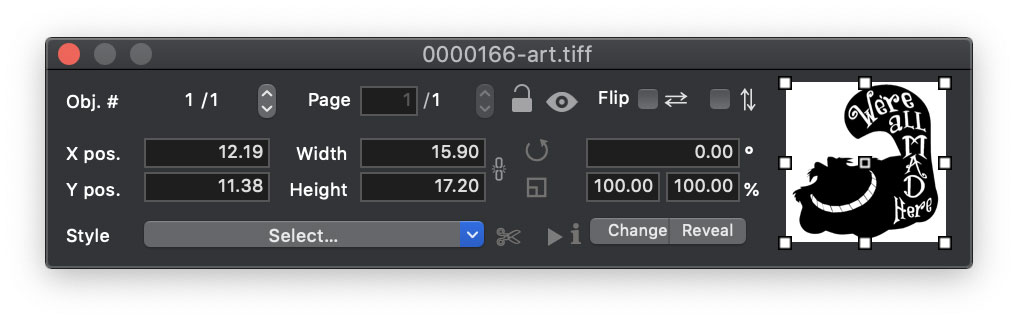
The info / edit panel
It brings a free rotation field, a free scale% field (on both axis, as an option), numerical positioning fields, width or height constrain fields, clip controls and other goodies and it is a powerful object editor/inspector.
Selections and super selections
When one or more objects are selected, a coloured ring surround them.
The ring colour may be orange or cyan (tough you can change these colors in the general preferences).
Cyan means that the object(s) is(are) part of a selection of more objects.
Orange means that the object is part of a selection and it is also the "super selected" one. Each selection has always one member that is super selected. This one is the object we are referring to with the info panel.
- You can use the stepper to cycle through the selected objects
Obj # 1/5
On the main window you should see, between the selected objects (cyan ring by default), one with a different selection ring color (orange by default). This, together with the little thumbnail in the info panel, should let you easily recognize which object the info panel is referring to.
- If the object is a pdf (or even a multipage tiff) with more than one page, you can choose here which page to display / print.
PDF page 1/5
You can use the stepper to cycle through the available pages. You can use the keys pageUp, pageDown, Home, End on the keyboard too.
- Use of the pivot point "
 ":
":
- You can numerically establish the position of an object writing numbers in the Xpos and Ypos fields. The object will get the new position in order to have its selected pivot in the just given Xpos and Ypos.
Note: handles refers, in this case, to the current object bounds (that will be different from thumbnail representation when the objects is rotated).
- While using rotation and scale fields, instead, the pivot has in the object the same position as in the thumbnail, being the hing for the operation.
- The same behavior (handles that follows possible rotation) we have on width and height operations, so if the object is rotated 90°, the width value we type refers, in this particular case, to the "visual" height. This may be deceptive, but so it is.
- You can numerically establish the position of an object writing numbers in the Xpos and Ypos fields. The object will get the new position in order to have its selected pivot in the just given Xpos and Ypos.
- The padlock button
 locks /
 unlocks objects. This may be useful to prevent unwanted moving.
- You can hide [
 ] or show [
 ] any selected element. This is useful when you want to select an object that is currently covered by another.
Just hide momentarily the above object. To show the hidden object again, either you click and drag a box around the area where it should be, or use the items list panel that has a column with the state of visibility for each object in the document.
Note: an hidden image is invisible to the view (and the print) but actively partecipates to all the operations where it is involved (packing / nesting, transformations etc.).
- Flip: vertical and horizontal symmetry operations are performed always on axis passing by the central pivot.
- The style popup: to show / edit the print style for the object.
You can choose one or more items between these:
Styles are a minimal add-on to your images. Most used are trims, transparency (on pdf, tiffs with mask, png with transparency), dashes and strokes, textual tags.
Tip: numeric fields Xpos, Ypos, width, height, angle, scale, clippings accept input of mathematical operations, automatically calculating the result. For example you can input 3+3*5 and it will turn out to be 18.
The Info/Edit Panel expanded
Click on the little arrow to expand the Info Panel and bring to visibility other important fields and controls:
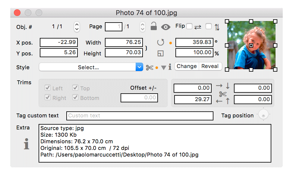
- Trim sides: trims (crop signs) can be applied independently an each of the four sides of an image. This is useful in imposition of adjacent images (for example in imposition, see booklets imposition or business cards imposition).
- The trim offset +/- field is used to offset trim marks from the border of the image. Negative values moves trims toward the center of the image, sliding on the border, positive values offset trims outside, the value 0 leaves the trims on the exact border of the image.
- The clipping fields: identified by the scissors icon, here you can edit image clips numerically.
- The Tag side slider (enabled if a text tag style is selected) orient the caption on one of the four sides of the image.
- The Custom text field (when custom text style is enabled) lets you type the desired custom text to show on the image side you select with the above tag side slider. The custom text can be concatenated with the other text styles (size, date, name and path).
- The Change link push button brings up the file browser letting you choice another image to replace the one the info panel is referring to.
- The Reveal push button show you where the image resides on your disk and alert you if the image is not found.
- Extra field gives you extra informations about the selected image.
Tip: When just imported, an object is at its "natural" shape represented by scale=100%, rotation = 0, all clips = 0. Modifying it (resize, clip or rotation), a little orange ●︎ point appears next to the modified fields to show the object has lost its originality. Resetting a value to the original, will cause the point to disappear.
The items list panel
To get better control of all elements in a FitPlot document, a new panel has been introduced with version 4.
You can activate it from menu Windows -> Show items list (cmd-ì).
Also in the toolbar you should see the push button ![]() that shows/hides the panel.
that shows/hides the panel.
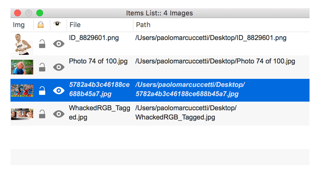
The items list panel
- You see inserted images in distinct rows, each showing a thumbnail, its lock state, its visibility state, image file name and image complete file path.
- When one or more image is / are selected on the document, relative rows are hilighted.
- Viceversa, clicking on a row in this panel makes a selection of the relative image in the FitPlot document.
- A double click on a row in the panel causes the "replace image" procedure to start, bringing up an open dialog to choose a replacing file.
- Clicking the lock icon on the row causes the relative image to be "protected" by any modification.
- Clicking the eye [] icon on the row causes the relative image to disappear from view. The image is, in this state, transparent to mouse click, but still selectable with the select all command [cmd-A], with a box select [click and drag around the area where the image it is supposed to be] or from this same panel.
- Clicking on the cross [] icon will bring back to visibility the image in the selected row.
Items list panel - Update 5.8
Since the version 5.8 this panel has been improved both in usability and clarity.
- It's now possible to move images back/front in the image levels just clicking / dragging and releasing a row onto another.
- A contextual menu for the most common operations has been added. It contains also the new function Reverse Stack Order.
Reverse Stack Order
This menu command [Tools -> Arrange -> Invert Stack Order] reverts the order of disposition of the images in the list and may be used in some occasions to get layouts of set of images (of the same sizes and orientation) correctly ordered after packing. For a discussion on this subject see the relevant page.